This section describes the basic concepts of VRML and must be understood before
going further in the content creation process.
The main concepts you have to learn are:
Warning:
Do not try to display 3D shapes at first.
This is tempting because you can find a lot of examples with Internet.
But this is misleading because MeMo is not a pure VRML browser, despite it is based on VRML.
You need a special way to declare 3D objects.
This is a very simple process but this will come later in this document to keep things simple and avoid confusion.
To write your first scene:
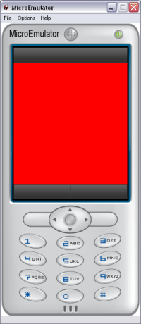
You should have the following output:
If you run this scene, you should see a red and solid rectangle covering the whole screen.
Warning:
Do not go further until you can compile and run successfully this scene.
VRML provides a simple formalism to describe a rich media interactive scene by giving a formal description of the graphical objects, animations and interactivity instead of providing a list of drawing instructions.br/> In consequence a scene is a graph made of nodes, like the next diagram.
Each node represents a functionality like:
By assembling nodes together you semantically combined nodes to create complex
objects which:
The functionality achieved by a node can be usually changed or specialized using
some properties, specific to this node, called fields.
A field has a name and a value, and this association is a very convenient,
declarative way to specialize the node behavior because the name is often self
expressive: a Rectangle has a size, a Material2D has a transparency level, a
Shape has both a geometry and an appearance.
For instance, to display an image, you first create a Texture node with its url
field set to the name of an image file. Then you create a Rectangle with the
appropriate size.
Finally you associate Texture and Rectangle by using them in a Shape containing
a green color.
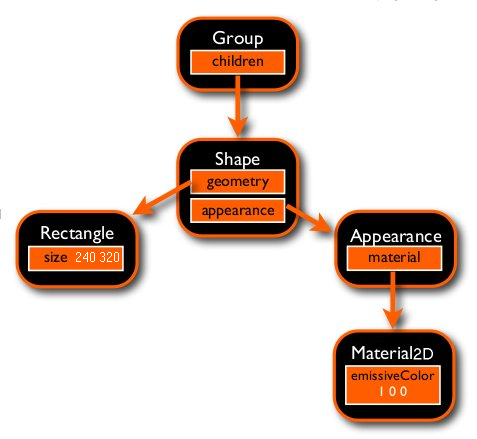
Finally you and associate it to a rectangle. Field values can be numbers
representing colors or transparency levels, strings for urls or other nodes. In
the figure below, nodes are in black and fields in orange. The value of the
field size of the node Rectangle is 10 20, while the value of the field
appearance of Node Shape is another node: Texture.
This tree of nodes can be textually described using a formalism called VRML and
would look like below:
A VRML player reads a file containing a scene description like the one above and creates an internal internal representation of this graph. You do not need to know how this is done, you just have to provide the textual description. Then the player navigates through this graph and interprets the meaning of each node according to both the value of its fields and user interactions. This is called the composition phase. Then according to these computations all geometric nodes are rendered. A player loops forever between these steps:
A node is defined by its type followed by the list of its properties (also called fields), enclosed in curly brackets (?{? and ?}'). A property consists in a name followed by an associated value. The type of a node is obviously describing the associated functionality.
Similarly, the name of the fields are supposed to describe themselves. However do not hesitate to check the official VRML documentation as some terms can be misleading, especially to beginners. Nevertheless, nodes are always defined using the following syntax:
For instance to define a rectangle of size 10 25, just write the following code will instantiate a new Rectangle node and set its size to 10 x 25:
TIP
in VRML space, tab and newline are just blank separators, use the indentation that
make the code clearer for you.
When the VRML player reads this description in a file, it will create a new instance of node, created from a model called Rectangle and set the value of its field size to 10 35. When evaluated later on, the new instance will have to provide the functionality of drawing a rectangle of the specified size, according to a current color, texture and geometric transformation. But this is the job of the player, you just have to provide the node type and the value of its fields.
For programmers, especially those used to Java or C++, it is always misleading at first to read something like:
This code means that a new Shape object has to be created, and that its field (or member) geometry is affected to a new node of type Rectangle. A Java style pseudo code could be something like:
However, as in languages like Java or C++, fields are strongly typed. This means that you cannot specify any kind of value for a field, you must strictly follow its type, which is a good thing because this detects a lot of errors when the graph is initially read by the VRML player (or the MeMo compiler).
The following table lists all the VRML types with an example. An element with a single elementary value starts with SF (Single Field), an array starts with MF (Multiple Field). You will note that an array by providing a list of elements, enclosed by square brackets ('[' and ']').
| Type | Value | Example |
|---|---|---|
| SFBool | boolean | TRUE/FALSE |
| SFInt32 | integer | 3 |
| MFInt32 | array of integers | [ 12, 4, 7 ] |
| SFFloat | float | 3.1416 |
| MFFloat | array of float | [ 12.5 23.2 ] |
| SFVec2f | couple of floats | 12.5 23.2 |
| MFVec2f | array of couples | [ 12.5 23.2, 0.7 11.9, 0 0 ] |
| SFVec3f | triplet of floats | 12.1 23.5 0.4 |
| MFVec3f | array of triplets | [ 12.1 23.2 35.6, 0.7 0.11, 0.34 ] |
| SFNode | node | Transform { ... } |
| MFNode | array of node | [ Shape { ... }, Group { ... } ] |
| SFColor | triplet of floats,in [0..1] | 1 0.4 0.1 |
| MFColor | array of colors | [ 1 0 0, 0 1 1, 1 1 1 ] |
TIP
the comma (,) is also a blank char like space. You can use it to visually
separate values in your array.
VRLM designers wanted to keep VRML simple that's why they defined a single type
for node: SFnode.
But you will save a lot of time if you understand that nodes can be split in
several, specialized, sub categories (for instance Rectangle,
Circle, IndexedFaceSet2D are all geometry nodes).
This notion of node categories is mandatory to understand because the syntax
would allow to set a SFNode with any node.
However, regarding of the field, you can set only a small subset of nodes. So semantically speaking, consider that nodes are typed and it will be easier to select which node can be set to a field.
A common mistake is to mix between node types and field names.
A node type always starts with an uppercase letter and a field name always start
with a lowercase letter. This is specially useful when you will see for the
first time: appearance Appearance { ... }.
This simply means that you affect a node of type Appearance to a field named
appearance.
This seems also strange because Appearance is the only node that can be set to
an appearance field.
TIP
fields have default values, so you only have to specify fields that you
want to change this default value.
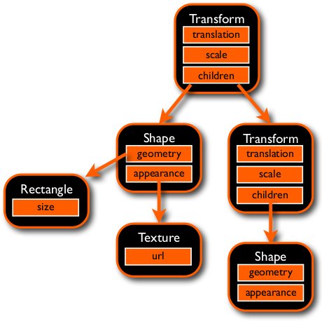
In the above diagram on the right, a scene is defined by a first geometric transformation (Transform), defined by a translation and a scale factor. This transformation will apply to several nodes (here two nodes: Shape and Transform), defined through the MFNode field called children.
Before creating fancy 3D graphics, you first have to learn how to draw 2D objects, like background, buttons, text, ...
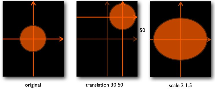
MPEG-4 specifications contain a 2D counterpart to VRML that was only 3D at the time it was defined (it became an ISO standard in 1997, and thus is also referred as VRML97). In MPEG-4, and thus in MeMo player, 2D objects dimensions (like radius, size, coordinates) are expressed in pixels. Those pixels are referenced in a 2D coordinate system by two axis centered at the exact middle of the screen. The X axis goes from left to right while the Y axis goes from bottom to top. This numbering of 2D axis is rather non conventional because it has been inherited from VRML and the way this format is dealing with 3D axis. However, the unit of an axis is fortunately a pixel. For instance, if your screen is 240x320, the X axis coordinates will go from -120 to 120, the Y axis from -160 to 160.
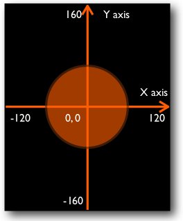
Each graphic objects (rectangle, circle) are drawn relatively to their center, co-incident with the axis center. In other words, each object is drawn centered to the point (0, 0) of the coordinate system. Hopefully, if you draw a rectangle of size 240 320 at the center of the screen, it will cover all the pixels. If you specify a circle with a radius of 60 you will get the above result. Despite many people prefer a (0, 0) point at the top left corner, this is relatively easy to get used to this system.
The first thing you will probably want to do is to draw shapes at a different
places in the screen and not only at the center! This is here that a new concept
appears: instead of specifying an offset between the shape and the coordinate
system center, you move the coordinate system and continue to draw the Shape
centered. There is no way to move a shape. This coordinate system transformation
is done using a node called Transform. This is very important to understand that
this node will modify the axis and there is no other way to move object in VRML:
you move the axis while the object has still its center co-incident with the
axis center. You can use the same mechanism when you want to shrink or expand a
shape: you just change the scale of the axis, using the scale field is like
changing the size of pixels, like shown on the figure below. Note that this axis
transformation will affect only the children of the Transform node. Transform
nodes can obviously nested. In this case the resulting axis is the cumulation of
all transformations.
The figure below shows the effect of the translation and
scale fields of transform on a circle (centered 0, 0 and of constant radius)
TIP
there is a simple formula to place an object from conventional image reference (the
top left corner is 0, 0): if W is the width of the screen, w the width of the object, and x the
conventional coordinate, then the VRML coordinate x' = (w/2 - W/2) + x
When you want to draw multiple shapes at the same position, you can specify them inside the same Transform. If they are both children of a transform, their will be affected by the same axis transformation. The shape defined first will be drawn first, the second defined will be draw afterwards (More generally, shapes that appear first in the VRML scene will be drawn first). This can be useful if you want to draw some text on top of a picture (i.e. a button label). If you want to draw shapes at different position, use different Transform nodes, one per Shape. Whether you have to imbricate them depends on their spatial relationship: if they are imbricated, moving the top one will affect all the children.
A shape in an assembling of nodes to define graphically an object. In the
examples above we saw a shape defining an orange circle. To define a shape we
use a Shape node, which is very simple as it has only two SFNode fields. The
first field, appearance, can only receive an Appearance node. The second,
geometry, can receive any geometry node:
Rectangle,
Circle,
Text,
IndexedFaceSet2D.
Shape makes the association between an appearance and a geometry.
An Appearance node can have two parts defined by corresponding fields, a
material and a texture. You usually only define one at a time. The
material field typically receives a Material2D node, the texture field can
receives an ImageTexture or a MovieTexture.
Material2D defines the shape color (emissiveColor), whether it is filled or
hollow (filled) and the transparency level (transparency).
ImageTexture is used to refer to an image through its path specified in the url field.
MovieTexture does the same but refer to movie clip. The supported media type depend of
the phone, but commonly image formats supported are JPEG, GIF and PNG. For movie
clips, H263, MPEG-4 SP are very common with H264 starting to spread. the maximum
movie format is usually 176x144 (some phones support 240x320 for MPEG-4 SP).
Note:
For Tiny Mobile Widgets, use small images (which take less space). To do:
- Remove alpha channel (transparency)
- Go to indexed color (48 colors, but depends on the rendering)
You should have now enough knowledge to write (at least understand) the following scene that displays an hollow orange square of 50 pixels shifted by 10 15 from the center of the screen.
TIP
you can put comments starting by # and ending at the end of the line. This will help
you (or someone else) reading this code later one.
If you want to display an icon instead of a solid color, you just have to change the definition of Appearance:
An example of cumulated transformation used to display two objects at the top of the screen. Note the the third Transform is only affected by the first one, the second one affecting only its own children. The resulting translation is -50 95 for the second Transform and 50 95 for the third one. This mechanism is specially useful with animation, as you can define an animation independently of an absolute position and use it anywhere on the screen by just putting it inside a Transform with the right translation.
In addition to translating and scaling you can also rotate the axis, but there are some incompatibilities with J2ME and you may only see your objects rotated by p/2 steps. This is especially true for text and images. You have more freedom with IndexedFaceSet2D.
To understand the concepts involved in animations, you first have to learn two other concepts DEF/USE and ROUTE. The first one is a way of giving a label to a node. This label can be anything you want but as its goal is to identify a particular node, it is usually a good idea to set a meaningful label (e.g. BUTTON_APPEARANCE, MAIN_TRANSFORM).
Warning: MeMo limitation
Geometry property (Shape node) does NOT support the DEF / USE.
You can use any combination of letters and numbers but a handy practice consists in using only uppercase letters and numbers to distinguish quickly these labels. You can but a label to any SFNode, you just have to precede the node type by DEF label, like in DEF MAIN_TRS Transform { ... }
Once a node has been DEFined, you can reuse it in numerous ways. You can reuse the same node several times in your scene, this save typing but also memory. To reuse a name just put USE label in place of a node definition. For instance if you use the same shape for a button background in several places, you can DEF the first one and replace the others by USE label, like in the example below:
Another mechanism involving DEF nodes is called ROUTE and consist in establishing a pipe between two fields of two different nodes. The pipe is acting as a value transporter between two fields: a soon as the value of the first field is modified, it is copied to the second one. This involves that the two fields have obviously the same type, non conversion is performed (but if you do need to convert values, this can be easily done using a script node). The declaration syntax is simple (do not forget the '.' between label and field names):
The routing mechanism works forever, as a background task; each time the left field is modified, its value is copied to the right field.
You can write your route virtually anywhere in the VRML file, the only limitation is that the nodes to be connected must have been defined BEFORE you declare the ROUTE.
TIP
you can read the line above as: automatic copy of fieldName1 of node referenced by
label1 to fieldName2 of node referenced by label2
For instance you can set a pipe between the radius of two circles by writing:
As soon as the radius of CIRCLE1 is modified (e.g. by a script), the radius of CIRCLE2 takes the same value.
TIP
labels are encoded by MeMo compiler, so you do not have to care of the memory they
can use. A very long label will use as memory as a very short one, so use long labels to
enhance readability of your VRML source.
Do not under estimate the power and usefulness of ROUTE mechanism
(despite the previous example is not very useful). ROUTE is the basis of all the
VRML animation framework as you will see in the next lines.
The VRML animation framework is also used in MPEG-4 and thus in MeMo. It is based on a pulse generator connected to interpolators that, in turn, are connected with fields of nodes. The connections are obviously done using ROUTEs.
The heart of the animation is a node called TimeSensor. It gives the beat of the animation by generating pulses and outputting values that will be used to animate fields. In a TimeSensor you can specify the length of the animation, when it starts and stops and whether the animation should loop or not.
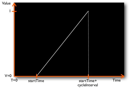
Times in VRML are expressed in seconds and the origin of the main clock (when time is 0) is 1970, January the first at 0h00. This is not very handy in practice so MPEG-4 and thus MeMo statued that the clock starts with the scene. So when the scene is started by the player, time equals 0 second. The length of the animation is specified in a field called cycleInterval, the time to start in startTime and the time to stop the animation in stopTime. When the main clock reaches the value of startTime, the TimeSensor begins to run and output a zero. The next time the time sensor is activated in the composition loop, the output value is equals to cycleInterval / (currentTime - startTime). This formula means that the output will grow linearly from 0 at startTime to 1 at startTime+cycleInterval as described in the following figure. The field that receives this computer value is named fraction_changed. You must use it later on to access the computed value. And of course ROUTE will be the mean to do that.
The big advantage of this method is that you are sure that something will be zero at the beginning, one at the end and something linear in between. Whatever the speed of the machine your player is running on you will be "exact time", with potentially just a few frames, but you will be in time. Imagine you want to make a square cross the screen in 3 seconds, you can compute a left position at zero, a right position at cycleInterval and position in between based on the TimeSensor output value.
An interpolator is specified with list of pairs. A pair associates a key with a keyValue. When you enter a number, a fraction (the exact field name is set_fraction), to the interpolator, it compares this fraction to the keys and outputs a value (the exact field name is value_changed). If the fraction matches exactly a key, the corresponding keyValue is used as value, if the fraction is in between two keys, a value is interpolated linearly according to the corresponding keyValues and the distance between the fraction and the keys. If we take the following example:
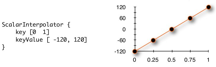
The intuitive result you would expect is ... right: as shown on the above figure, at the middle of the animation you will get 0, at 1/4, you will get -60 and at 3/4 you will get 60. The exact formula is, considering that fraction is in between k1 and k2 and the corresponding key values are kv1 and kv2:
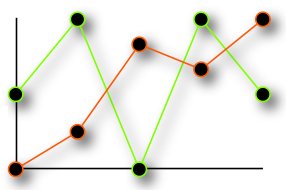
Further you are not limited nor in the number of keys, neither in the key values as shown in the figure below. The only thing that you cannot control is the interpolation is LINEAR between two key values.
TIP
always specify a key at 0 and a key at 1. Most of the
time this is enough to specify a simple animation but your
are free to put whatever you need in between: for instance,
by adding keys at the right places, you can simulate
acceleration, slow down, rebounds, springs, fade in or
fade out, back and forth effects ...
Other sensors work exactly the same way except that not only a single value is interpolated but a color, a vector, a 3D angle ... Refer to the VRML documentation for exact details but in essence they are all working the same, including the way you connect them to TimeSensor and other nodes.
Putting everything together is now really simple. We have to define a TimeSensor, an interpolator and a node with a property to be animated. For instance, if we want to animate the color of a rectangle from orange to black in 2 seconds starting one second after the beginning of the scene, we must write the following code:
The main concept behind the script node is that some javascript code is interpreted when an event occurred, i.e. a value is carried on by a ROUTE to the script. For that, a Script node allows you to define your own, new fields and associate a javascript function that is automatically triggered when a ROUTE copy a value to the new field.
There is a very convenient way to simplify your VRML application: reducing your code by using prototypes. A PROTO is a way to group a small sub-scene as it was a new node with its own fields. For instance, if you want to display some fancy text with a show-like effect, you would prefer to write:
instead of writing the following code each time you want your fancy text:
The PROTO is the answer! To define a proto you have to give its name, the list of its parameters (the new fields) and its body. the only trick to understand is how to link parameters to fields inside a body. This is done by using the IS keyword. It is acting like the USE keyword but work with any field. This means that the field used in the body will be the exactly same as the one in the parameter section. Exactly means that they will all share the same memory. If one is modified (using a script) all the others are also instantaneously modified. In the same way, if you route a value to a field of your proto, all internals fields ISed to the modified parameter will be also modified. Once you have a piece of code that you want to modify, just wrap it with the proto definition like below:
You can notice that as with the Script node, you have to specify the scope of the parameter fields. The value is also important and acts as a default value. If you do not set a new value for a field when using a proto, the default value is used.
TIP
you can use the same name in the parameter and in the body, the compiler will not be
confused and this will help you to remember the name of your proto fields, by calling a
translation "translation".
You can create protos libraries by defining your protos in a separate file. For instance you can save the above proto in a file named MyText.wrl. If you want to use it in you scene, just declare it at the beginning of the file with the EXTERNPROTO keyword, specifying the name of the proto, its parameter fields and the name of the file containing the actual definition of the proto. This was needed in VRML but as the MeMo compiler reads the file to get the definition at compile time, you do not need to specify the parameters, they are automatically extracted. So instead of writing this:
Just write that:
TIP
If it appears that you inline several scenes that share the same proto, using
EXTERNPROTO will save space because the proto definition is stored only once in the
phone memory.
Switch node allows to render only
one node in a list of nodes. It is useful to display or hide elements.
It can be used to manage different panels in a scene (with tabs, menu, ...).
Switch node contains an array of
nodes (choice attribute) and the displayed node (whichChoice attribute).
whichChoice contains the index of current displayed node in choice
array. First node index is 0. Switch node
doesn't display node if whichChoice = -1.
whichChoice value is modifiable via script (Script node and javascript language).
See Switch node documentation for more information about Swith node and example.
Goal: separate the application into multiple sub scene.
Two nodes used for the implementation, Inline and Anchor.
Note:
The inlined scene can be replaced by another sub scene via Anchor.
Inline and Anchor are complementary.
Warning:
For Inline and Anchor nodes, use M4M files in URL field.
Don't use WRL files ( cause problems during the
final M4M file creation).
Inline node can be use with the
Switch node.
Avantage, only the displayed node is loaded in memory. Other subscenes are not
loader.
Inconvenience, change the subscene is slower (when whichChoice attribute
of Swith node change). Inline node must load and construct the new subscene.
Example:
The Main scene (main.wrl file):
The sub scene (square.wrl file):
For informations about inlining, see advanced development part.
The Anchor node has two roles:
Note:
MicroEmulator doesn't open web browser.
Example:
For code example, see tutorials chapter.